Instruction Set
Format of a Standard Assembler Program
DOSSEG
.MODEL SMALL
.STACK 4096
.DATA
; data definitions
.CODE
ProgramStart:
; assembler instructions
mov ax,SEG _DATA ; set up data segment
mov ds,ax
mov ah,4ch ; terminate program
int 21h
END ProgramStart
This is only valid for simple assembler programs that are of the
small, non-memory resident variety. For larger programs the .MODEL
directive can be LARGE or HUGE or COMPACT. The .STACK directive
indicates the number of bytes to reserve for the stack of the
program. If this number is omitted, the stack defaults to 1k.
Except for the commands to terminate the program, all the other
commands are what is termed Assembler Directives. These instruct
the assembler on how to assemble the program, without generating
any actual assembler code.
All names that are used in the program are converted into memory
locations during the assembly process. Thus, any name is generally
considered to be analogous to a memory location while writing
assembly code.
Data definitions
Within the .DATA section, data items can be defined together with
initial values. All declarations are of the form:
The Name is used to refer to the data thereafter. The DataType
can be either DB (byte) or DW (word). This defines what the assembler
should consider as the data type of the first item of data. All
other items of data on that line inherit the same data type. There
are a number of other data types but DB and DW are the most common.
Value can be used to set an initial value/s for the data item.
This can be set to "?" to instruct the assembler that
no specific value need be assigned to that data item.
The MOV instruction
The MOV instruction is the most important command in the 8086
because it moves data from one location to another. It also has
the widest variety of parameters; so it the assembler programmer
can use MOV effectively, the rest of the commands are easier to
understand.
format:
MOV destination,source
The possible combinations of operands are as follows :
| destination | source
| example |
|---|
| register | register
| mov ax,bx |
| register | immediate
| mov ax,10h |
| register | memory
| mov ax,es:[bx] |
| memory | immediate
| mov aNumber,10h |
| memory | register
| mov aDigit,ax |
MOV copies the data in the source to the destination. The data
can be either a byte or a word. Sometimes this has to be explicitly
stated when the assembler cannot determine from the operands whether
a byte or word is being referenced.
The MOV instruction has a few limitations:
- an immediate value cannot be moved into a segment register
directly (i.e. mov ds,10)
- segment registers cannot be copied directly (i.e. mov es,ds)
- a memory location cannot be copied into another memory location
(i.e. mov aNumber,aDigit)
- CS cannot be copied to (i.e. mov cs,ax)
These limitations can be overcome using indirect data movement
through a general purpose register as illustrated in the general
format given above.
Each of the possible values for the destination and source is
called an address. From the above table it becomes apparent that
there are a number of different addressing modes (immediate, register,
memory).
Addressing Modes
- Immediate Addressing
This is when a constant value is moved into a register or memory
location. It is not really an address since it does not point
to any location within the memory or CPU. Immediate addressing
can only be used for the source since immediate values are not
themselves stored anywhere; during assembly of the program, the
immediate value becomes part of the machine code instruction.
example: mov ax,10h
- Register Addressing
A register can be used as both the source and destination of the
instruction. Registers are very fast for most operations so maximum
use must be made thereof.
examples:
mov ax,bx
mov ax,10h
mov si,es:[bx]
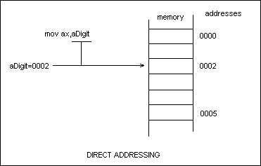
- Direct Memory Addressing
A memory location can be used by using its address as the operand
in an instruction.
example: mov ax,aDigit
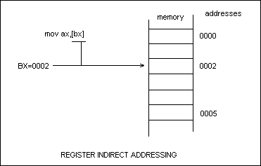
- Register Indirect Addressing
Instead of specifying the memory location as an operand, the memory
location can be stored in a register. Then this register must
be specified to access the memory. For indirect addressing, the
8086 can only use the BX, BP, SI and DI registers.
example: mov ax,[bx]
Note that the difference between this and Register
Addressing is the use of the square brackets ([]) which distinguish
a normal register from a memory location.
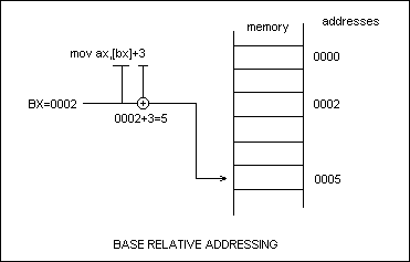
- Base Relative Addressing
A possible combination of direct and indirect addressing techniques
could be when an indirect address is specified as well as an offset
from that value. To specify base relative addressing, the programmer
must indicate the base register and displacement/offset as a sum.
examples:
mov ax,[bx+4]
mov ax,[bx]+4
mov ax,4[bx]
All these instructions will use the same address,
which is 4 more than the address stored in the bx register. The
only registers allowed are BX and BP (the so-called "base"
registers). This technique can also called Direct Indexed Addressing,
when it utilises the SI and DI registers (the so-called "index"
registers).
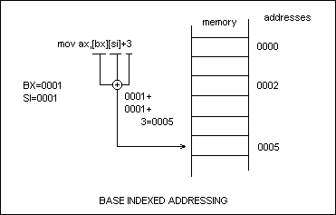
- Base Indexed Addressing
This is a combination of base register and direct indexed addressing.
Instead of specifying the address as being stored in one register,
the CPU can add the values stored in two registers to get the
effective address. Of course, an offset can also be specified.
Since this technique uses a base register and an index register,
there are only four allowed combinations of registers.
example:
mov ax,[bx+si+4]
mov ax,[bx][si]+4
mov ax,[bx][si+4]
All these instructions will use the same address.
If BX=4 and SI=8, then the address will be 4+8+4 =16 (decimal)
= 10h.
Base indexed addressing is useful for indexing two-dimensional
arrays, whereas the other methods are used for the simpler one-dimensional
cases.
Complete Table of Addressing Modes
| displacement only |
| BX + displacement |
| BP + displacement |
| SI + displacement |
| DI + displacement |
| BX + SI + displacement |
| BX + DI + displacement |
| BP + SI + displacement |
| BP + DI + displacement |
Example usage of non-trivial addressing modes
Index registers can be used just like array indices in high-level
languages. Assume that an array of bytes is stored in memory at
location anArray. Then, to access the second element, we need
to use the address anArray+1. To access the second element, we
use anArray+2 ... etc. In order to access an arbitrary element
we can use a variable index eg. BX. Thus we need to index anArray+BX.
Written in assembler, this translates to anArray[BX] or [anArray+BX]
or [BX]+anArray.
Segment Over-riding
Instead of all references to memory being taken from the DATA
segment, the programmer can explicitly tell the assembler to read
a memory location using a different segment. To do this, the name
of the segment must be prepended with a ':' to the address.
example: mov ax,ex:[bx]
This calculates the effective address using the ES register instead
of the DS register which is normally used. Similarly, the CS register
can be overridden when required. This is normally used when a
memory location in another segment needs to be accessed. Rather
than change the DS register unnecessarily, ES could be used for
that purpose.
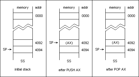
The Stack
The 8086 uses a simple stack in memory for the storage of temporary
data. It also uses this stack to store the return addresses when
it enters a new procedure. All values on the stack are 16-bit
words. The registers that manage the stack are SS, SP and BP.
- SS denotes the segment of the stack
- SP (stack pointer) points to the last element on top of the
stack
- BP (base pointer) points to the bottom of the stack. This
is used to set up and manage information on the stack during a
procedure call.
The stack grows downwards during its typical operation. This means
that when more elements are added to the top of the stack, the
value of SP decreases. When the stack is set up, SP points to
the largest value on the stack. For the sample code at the beginning
of the chapter (.STACK 4096), SP would be set to point to 4094
at the beginning of the program - 4094 is two bytes from the end
of the stack, which is at location 4095 since all segments start
at location 0.
There are a few commands which allow the programmer to store and
retrieve values from the stack.
The PUSH/POP instructions
format:
PUSH source
POP destination
The possible operands are as follows :
| source | example
|
|---|
| register | push ax
|
| pop ax |
| memory | push es:[bx]
|
| pop es:[bx]
|
PUSH decrements the SP register (by 2) and copies a value onto
the top of the stack. POP retrieves the value from the top of
the stack and stores it into the destination, then increments
the SP register (by 2).
PUSH and POP can be used to save and restore the values of registers
when the register needs to be used for some other function temporarily.
example:
push ax
mov ah,09h
mov dx,OFFSET aMessage
int 21h
pop ax
Here the value of AX is probably crucial but AX has to be used
in order to output a message. So its contents are saved on the
stack and restored after the interrupt procedure is called.
The LEA instruction
format:
LEA register,memory
Load Effective Address loads the specified register with the offset
of a memory location.
The following two lines of code are identical:
mov ax,OFFSET aMessage
lea ax,aMessage
However, the MOV instruction cannot be indexed because OFFSET
is an assembler directive, not an instruction. It would be impossible
to say
mov ax,OFFSET aMessage+[BX]
since the offset calculation is done at assembly-time. On the
other hand, it is possible to issue the command
lea ax,aMessage[BX]
example:
lea dx,aMessage
mov ah,09h
int 21h
Notice that this is the same standard method of outputting a string
to the screen. It is preferred to use the LEA instruction in such
situations, making offsetting of the string easier in future.
Flags
The flags are a set of variables in the CPU which indicate the
status of various calculations and components of the CPU. Flags
are used, among others, in the following contexts:
- to indicate errors
- to indicate the sign of the last calculation
- to enable a carry during arithmetic operations
- for debugging
A number of instructions perform certain tasks based on the current
state of the flags. The most commonly used flags are:
| CF | carry flag
|
| ZF | zero flag
|
| SF | sign flag
|
| OF | overflow flag
|
| IF | interrupt enable flag
|
| DF | direction flag
|
The PUSHF/POPF instructions
format:
PUSHF
POPF
These instructions save and restore all the flags to/from the
stack. This preserves the flags when the code about to be executed
is going to modify crucial flags.
example:
pushf
call bigadd ; call procedure
popf
External/Public assembler directives
In order to incorporate procedures written in separate files,
the programmer needs to include PUBLIC directives in the procedure
file and EXTRN directives in the main program file. The secondary
procedure file need not have a program entry point since it cannot
be used on its own. Assuming that a procedure called readsint
has been defined to read an integer into the AX register. This
procedure is then exported by including the following line at
the top of the code in the secondary file:
PUBLIC readsint
Similarly, the program that is going to use this procedure must
include a statement telling the assembler that it is going to
use a procedure from an external file. To do this, the following
line must be included at the top of the main program source file:
EXTRN readsint:proc
Multiple declarations can be separated by commas
eg. EXTRN readsint:proc,writesint:proc
After both files are assembled separately, the files must be linked
together with a command such as:
TLINK MAIN.OBJ SECOND.OBJ
The IOASM library provides the following two procedures that can
be incorporated into your programs to make input and output simpler:
readsint - reads an integer into the AX register
writesint - writes the value of the AX register to standard output
To link your programs with IOASM, you need to include the following
line at the top of your program:
EXTRN readsint:proc, writesint:proc
and then link the program with the command TLINK YOURFILE IOASM.LIB
Sample Program #4
; simple numerical output program
DOSSEG
.MODEL SMALL
.STACK 4096
.DATA
Number1 dw 12
Number2 dw 24
Number3 dw 36
.CODE
EXTRN writesint:proc
; use procedure from IOASM to output number to screen
ProgramStart:
mov ax,SEG _DATA
mov ds,ax
mov bx,Number1 ; illustrate MOV instruction
mov ax,bx
call writesint ; call procedure to output number
mov ax,Number2 ; illustrate PUSH/POP instructions
mov bx,ax
push bx
mov ax,0
call writesint ; call procedure to output number
pop ax
call writesint ; call procedure to output number
mov ah,4ch
int 21h
END ProgramStart
This program simply loads a memory location into the AX register
and outputs it using the procedure built into the IOASM library.
The second part of the program loads a value into the AX register
and then pushes this value onto the stack. The AX register is
cleared and the value is popped off the stack. The point of this
exercise is to prove that the stack really does preserve the value
put onto it.
The ADD instruction
format:
ADD destination,source
The legal operand combinations are as follows:
| destination | source
| example |
|---|
| register | immediate
| add ax,10 |
| register | register
| add ax,bx |
| register | memory
| add ax,es:[bx] |
| memory | register
| add es:[bx],ax |
ADD adds the contents of the source to the destination. The source
and destination may be either bytes or words but both operands
must be the same type or the assembler will generate an error.
If the sum of the two numbers cannot fit in the destination, an
extra bit is required and this is signalled by the ADD operation
setting the carry flags (CF) to 1. If the sum fits without spillage,
CF=0. Other registers can be affected by addition operations as
well; ZF=0 if the sum is zero, SF=1 if the sum is negative, etc.
The logic of the basic addition command is:
destination = destination + source
In the case where a carry bit is being introduced into the calculation
from a previous calculation, the ADC instruction must be used
instead of ADD, and the logic is:
destination = destination + source + carry
The SUB instruction
format:
SUB destination,source
The legal operands combinations are the same as for addition.
SUBtracts the source value from the destination. Operation is
almost identical to addition, except that the CF flag is used
as a borrow in the case of the SBB (subtract with borrow) instruction.
The logic of the SUB instruction is:
destination = destination - source
and the logic of the SBB instruction is:
destination = destination - source - carry
The INC/DEC instructions
format:
INC destination
DEC destination
INC increments the source by one. Rather than use an ADD to increment
a register or memory location, the INC instruction does the job
faster and takes only parameter. Similarly, DEC decrements the
source by one. These are an example of the many instructions that
can be replaced by a sequence of other instructions; they are
used to speed up common operations.
The MUL instruction
format:
MUL source
MUL multiplies the source with the accumulator. If the source
is a byte-register or memoy location, the other element used in
the multiplication is the AL register - the product is then stored
in the AX register. If the source is a 16-bit word, the AX register
is automatically used as the second parameter and the product
is stored in the DX:AX register pair. This means that the DX register
holds the high part and the AX register holds the low part of
a 32-bit number.
The DIV instruction
format:
DIV source
DIV divides the accumulator by the source (which is used as the
divisor). If the divisor is a byte-register of memory location,
the AX register is used as the dividend and quotient is stored
in the AL register - the remainder is stored in the AH register.
If the divisor is a word, the DX:AX 32-bit register pair is used
as the dividend and the quotient is stored in the AX register
- the remainder is stored in the DX register.
The DIV instruction must be used very carefully because of the
potential risks of dividing by zero. If the divisor has a value
of zero, the CPU generates a "Divide by zero" interrupt
which, in most cases, will cause the computer to halt the executing
program (at the very least).
Sample Program #5
; simple numerical calculation program
; calculate (x^3 + 4) mod y
DOSSEG
.MODEL SMALL
.STACK 4096
.DATA
Number1 dw ?
Number2 dw ?
Four dw 4 ; constant
crlf db 13,10,'$' ; carriage return/linefeed
.CODE
EXTRN readsint:proc,writesint:proc
; use procedure from IOASM to output number to screen
ProgramStart:
mov ax,SEG _DATA
mov ds,ax
call readsint ; read in X
mov Number1,ax
lea dx,crlf
mov ah,09h
int 21h
call readsint ; read in Y
mov Number2,ax
lea dx,crlf
mov ah,09h
int 21h
mov ax,Number1 ; X
mov dx,0
mul Number1 ; X*X
mul Number1 ; X*X*X
add ax,Four ; X*X*X + 4
div Number2 ; (X^3 + 4) div Y
mov ax,dx ; output remainder
call writesint
lea dx,crlf
mov ah,09h
int 21h
mov ah,4ch
int 21h
END ProgramStart
This programs inputs two variables (X and Y) and calculates the
value of the expression:
(X^3 + 4) mod Y.
The AND instruction
format:
AND destination,source
The legal operands for this instruction are the same as those
for the ADD instruction.
AND performs a bitwise AND on the source and destination operands
and stores the result in the destination operand. It is useful
to check the various bits in a particular byte/word.
example:
and ax,0008h
After this instruction, AX will be greater than 0 only if bit
3 is set.
example:
and ax,FFF7h
In this case, the AND instruction can be used to clear bit 3.
The OR instruction
format:
OR destination,source
The legal operands are the same as for ADD. OR performs a bitwise
OR on the source and destination and stores the result in the
destination.
example:
or ax,0008h
This sets bit 3 in the AX register.
The XOR instruction
format:
XOR destination,source
Performs an Exclusive-OR operation on the source/destination and
stores the result in the destination register.
example:
xor ax,bx
xor ax,ax
The second example is an interesting, faster than usual, method
of clearing a register.
The SHR/SLR instructions
format:
SHR destination,1
SHR destination,CL
SHL destination,1
SHL destination,CL
SHR shifts the destination right bitwise either 1 position or
a number of positions determined by the current value of the CL
register. SHL shifts the destination left bitwise either 1 position
or a number of positions determined by the current value of the
CL register. The vacant positions are filled by zeros.
example:
shr ax,1
shl ax,1
The first example effectively divides ax by 2 and the second example
effectively multiplies ax by 2. These commands are faster than
using DIV and MUL for arithmetic involving powers of 2.
Sample Program #6
; simple numerical calculation program
; calculate (x and y) / 32
DOSSEG
.MODEL SMALL
.STACK 4096
.DATA
x dw ?
y dw ?
Five db 5 ; constant
crlf db 13,10,'$' ; carriage return/linefeed
.CODE
EXTRN readsint:proc,writesint:proc
; use procedure from IOASM to output number to screen
ProgramStart:
mov ax,SEG _DATA
mov ds,ax
call readsint ; read in X
mov x,ax
lea dx,crlf
mov ah,09h
int 21h
call readsint ; read in Y
mov y,ax
lea dx,crlf
mov ah,09h
int 21h
mov ax,x ; X
and ax,y ; X and Y
mov cl,Five
shr ax,cl ; (X and Y) / 32
call writesint ; output result
lea dx,crlf
mov ah,09h
int 21h
mov ah,4ch
int 21h
END ProgramStart
This program is very similar to the previous example. The difference
is that the formula being evaluated is (x and y) / 32. The division
is implemented as a SHR rather than a DIV.
The JMP Instruction
format:
JMP target
Unconditionally jumps immediately to the next instruction following
the target label. This is used to generate loops and perform selection
within an assembly language program.
example:
start:
lea dx,aMessage
mov ah,09h
int 21h
jmp start
This piece of code will output the message and then jump back
to the top of the code and repeat its action. It will, in fact,
produce an endless loop with messages being written to the screen.
The CMP Instruction
format:
CMP destination,source
Compare the numerical value of the destination with the source
and set flags appropriately. This comparison is carried out in
the form of a subtraction to determine which of the operands has
a greater value. After a CMP instruction, OF, SF, ZF and CF are
set appropriately. For example, if the operands have equal values,
then ZF if set.
These flags can then be interpreted by the various conditional
JUMP instructions and decisions can be taken on that basis.
The JUMP Instructions
example format:
JE target
The conditional jump instructions will execute a jump on the basis
of the previous CMP instruction. The operation of the flags can
be virtually transparent if meaningful names are used for the
jump instruction. For example, JE will jump if the previous comparison
yielded an equality. JNE will jump if the previous comparison
was unequal. If the jump is not executed, the following instruction
is executed as normal.
| JA | jump if destination above source
|
| JAE | jump if destination above or equal to source
|
| JB | jump if destination below source
|
| JBE | jump if destination below or equal to source
|
| JE | jump if destination equals source
|
| JNE | jump if destination not equal to source
|
There are many more jump instructions but most situations will
be covered by those above.
Conditional Jump instructions can only jump to a location that
is physically within 128 bytes of the point from where the jump
is taking place. This means that the jump must be to a nearby
location. JMP has no such limits so the two instructions can be
used in tandem to write effective decision-making algorithms in
assembler.
example:
cmp ax,bx
je thenpart
elsepart:
mov cx,2
jmp endpart
thenpart:
mov cx,1
endpart:
This is equivalent to the following line of pascal code:
if (ax=bx) then cx:=1 else cx:=2;
This can be expanded to simulate the equivalent of a pascal "case"
statement.
Procedures
Procedures in assembly language are declared with a PROC directive at the beginning and an ENDP directive at the end.
example:
TestProc PROC
mov ax,0
ret
TestProc ENDP
All procedures have a RET instruction at the end. This restores control to the point after which the procedure was called in the main program body.
After declaring the procedure, it can be called with a CALL instruction.
example:
CALL TestProc
The CALL instruction saves the address of the next instruction onto the stack and then changes the IP to reflect the value of its parameter. Since the IP keeps track of the currently executing instruction, this change causes the program to jump to the beginning of the procedure. When the RET instruction is encountered, it pops the old IP value off the stack, thus causing procedure to return to the main program body.
The CALL instruction can also take a register or memory location as a parameter. In this situation, the register/memory location contains the address of the procedure to be called.
FAR/NEAR type modifiers
In certain cases, procedures are defined in segments other than the one from which the procedure is called. In this case, simply saving the IP will not be enough to remember the point of calling; the segment has to be saved as well. The definition of the procedure must be changed to reflect that it is a FAR (meaning: not in same segment) procedure.
TestProc PROC FAR
mov ax,0
ret
TestProc ENDP
To call a procedure that is known to be in another segment, the CALL statement can also be modified using a FAR type modifier.
example:
CALL far ptr TestProc
Sometimes, it helps to explicitly define a procedure as NEAR (meaning: in the same segment) to create smaller programs. The unconditional JMP instruction can also take such FAR/NEAR type modifiers.
BYTE/WORD type modifiers
These modifiers are used to explicitly state whether a memory location stores a byte or a word. It is used in cases where the assembler cannot determine from the parameters whether a byte or word should be stored or referenced.
example:
mov ax,word ptr ES:BX
Sample Program #7
TestProc PROC
mov ax,4
ret
TestProc ENDP
ProgramStart:
mov ax,SEG _DATA
mov ds,ax
mov ax,5
call writesint
call TestProc
call writesint
This program demonstrates how to define and call a procedure. The top and bottom portions of the program have been omitted from the listing as they are fairly standard.
Sample Program #8
mov ax,11h
jmp Label3
Label1:
cmp ax,11h
jne TheEnd
mov ax,1
jmp TheEnd
Label2:
mov ax,2
jmp TheEnd
Label3:
cmp ax,10h
je Label2
jmp Label1
mov ax,3
TheEnd:
call writesint
This program shows how control can be transferred within the program depending on the values of a register.
The LOOP instruction
format:
LOOP target
Analogous to the "for" instruction in pascal is the LOOP instruction in assembler. The LOOP instruction runs a loop for a pre-specified number of iterations. The CX register is used to contain the number of iterations. Each time the LOOP instruction is encountered, it decrements CX and checks if it has reached zero. If it has, then control goes to the following instruction; if not, a jump is made to a specified point.
example (for):
mov cx,10
xor ax,ax
addstart:
add ax,cx
loop addstart:
This simple loop finds the sum of the first ten numbers using an iterative technique. In order to write loops analagous to the "while" or "repeat" pascal statements, it is advisable to use a CMP instruction coupled with an appropriate conditional jump.
example (repeat):
mov cx,10
xor ax,ax
addstart:
add ax,cx
dec cx
cmp cx,0
jne addstart
example (while):
mov cx,10
xor ax,ax
addstart:
cmp cx,0
je addend:
add ax,cx
dec cx
jmp addstart
addend:
The INT instruction
format:
INT num
INT calls the relevant interrupt procedure as specified by the num parameter. Any DOS or BIOS software interrupt can be called using the INT instruction. Sometimes it may be necessary to set certain values into specific registers to pass parameters to the interrupt routine.
example:
INT 21h
21h is the most common interrupt because it provides input and output services to DOS programs.
The structure of an interrupt procedure is like any normal procedure as far as the assembler is concerned. However, when performing an INT, the 8086 does a number of additional tasks, like saving the flags. Thus, instead of a RET instruction at the end of the procedure, every interrupt routine has an IRET instruction at the end. This IRET does the additional processing required (viz. restoring the flags) before returning control to the calling program.
The NOP Instruction
NOP (No OPeration) takes no parameters and does nothing. It is normally used for debugging only.
The MOVSB/MOVSW Instructions
example format:
REP MOVSB
REP MOVSW
These instructions are used to copy a block of bytes/words from one location in memory to another. The source is pointed to by DS:SI and the destination is pointed to by ES:DI. These register pairs are the only ones that can be used with string instructions such as MOVSB/MOVSW.
The REP prefix is used in conjunction with the actual instruction to repeat the MOV operation for the length of the block; it is similar to the LOOP instruction. In order to use REP, CX must first be set to the number of elements (bytes/words) in the block.
example:
mov cx,100
lea si,Source
lea di,es:Dest
cld
rep movsb
CLD clears the direction flag. This tells the 8086 that it must increment the SI and DI register after each iteration. If the direction flag is set instead of being cleared (using STD) then the 8086 will decrement SI and DI after each iteration. This creates the effect of copying a block in reverse.
Other Instructions
| CMPS |
compares two string in memory |
| SCAS |
scans a string for an element |
| LODS |
loads an element from a string |
| STOS |
stores an element into a string |
| IN |
inputs a value from a hardware port |
| OUT |
outputs a value to a hardware port |
| AAA |
ascii adjust for addition |
| AAD |
ascii adjust for division |
| AAM |
ascii adjust for multiplication |
| AAS |
ascii adjust for subtraction |
| CBW |
convert byte to word |
| CWB |
convert word to doubleword |
| DAA |
decimal adjust for addition |
| DAS |
decimal adjust for subtraction |
| CLC |
clear carry flag |
| STC |
set carry flag |
| CLI |
clear interrupt flag |
| STI |
set interrupt flag |
| CMC |
complement carry flag |
| DAA |
decimal adjust for addition |
| DAS |
decimal adjust for subtraction |
| JCXZ |
jump if CX equals zero |
| JG |
jump if greater |
| JGE |
jump if greater or equal |
| JL |
jump if less |
| JLE |
jump if less or equal |
| LDS |
load pointer using DS |
| LES |
load pointer using ES |
| LOOPE |
loop while equal |
| LOOPNE |
loop while not equal |
| NEG |
negate |
| NOT |
logical NOT |
| ROL |
rotate left |
| ROR |
rotate right |
| REPE |
repeat while equal |
| REPNE |
repeat while not equal |
| XCHG |
exchange two operands |
| XLAT |
translate using table |